Document LTM0893 rev 2.1f
Plumbing Diagrams
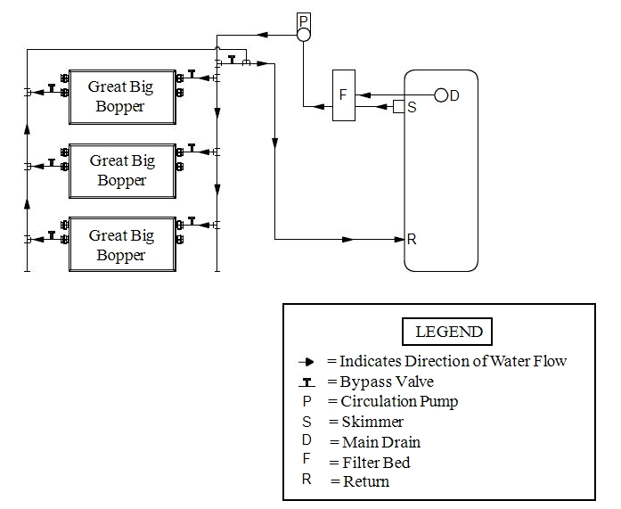
Plumbing diagrams are provided in this section as a planning guide to the sequence of equipment, valves, and fittings.
- The basic plumbing configurations for typical installations are shown.
- If the installation does not closely follow any of the supplied plumbing diagrams, AquaCal® Technical Support is available for installation advice and guidance.
- Confirm water provided to heat pump is clean and filtered.
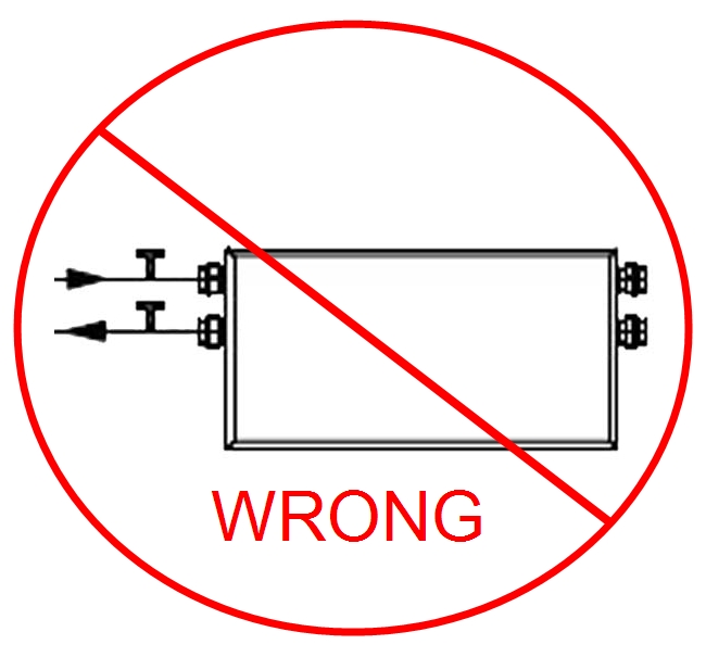
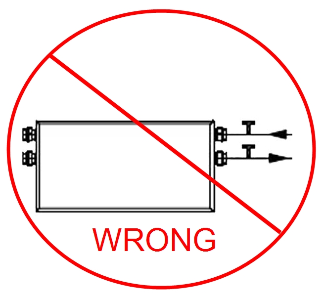
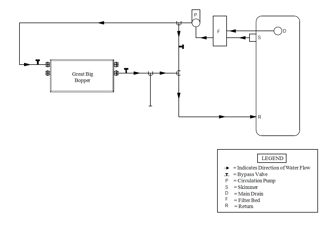
DO NOT PLUMB IN AND OUT WATER SUPPLY ON THE SAME SIDE
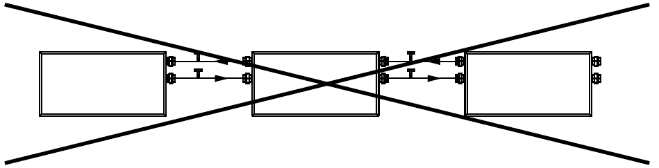
DO NOT PLUMB UNITS IN SERIES AS SHOWN HERE
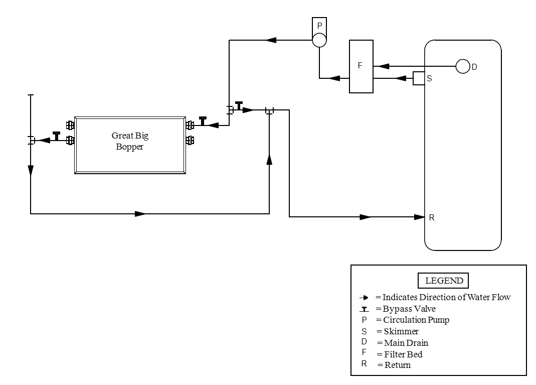
Great Big Bopper®
Single Unit - Example 2
While multiple Great Big Bopper®heat pumps are shown in the following diagrams, it is not a requirement. Sizing requirements will determine the number of required heat pumps.
Great Big Bopper® Multiple Units - Z-Flow Plumbing Design
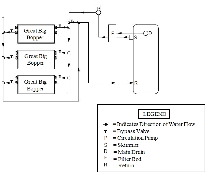
Great Big Bopper® Multiple Units - U-Flow Plumbing Design