Document LTP0114 rev 1.04
Connecting Smart Bus Controllers
DANGER
Failure to heed the following will result in injury or death.
- Risk of Electric Shock. Deactivate power while routing wiring to control board.
- Follow all National Electric Codes (NEC) and / or State and Local guidelines.
WARNING
Failure to heed the following may result in injury or death.
- This section is only for qualified installers who are familiar with swimming pool and spa safety standards.
- The installer must be familiar with service industry techniques.
NOTICE
Failure to heed the following may result in damage to equipment.
- Do not use electric heater connection on external controllers for heat pump wiring. This can cause damage to external controller, heat pump, and pad equipment. This damage is NOT covered by warranty.
- The wire size connecting the external controller to the heat pump must be 22-gauge, 2-conductor, low-voltage wire.
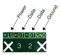
- Use the two middle data lines on the external controller's standard communication port (RS-485). Do not use the outside power or ground connection on the port.
Wire Connections
Standard External Controller Communication Port
- Deactivate power to heat pump and external controller.
- Remove electrical access panels on heat pump and external controller.
- Route 22-gauge, 2-conductor, low-voltage wires from the external controller communication port (com port) to the low voltage side of the heat pump's electrical enclosure. Do not use the power or ground wire.
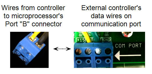
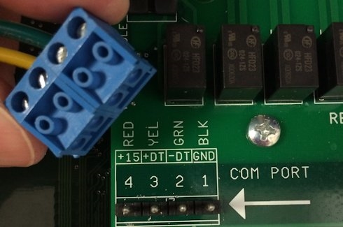
- Connect control wires to the heat pump's "Port B" of the microprocessor as indicated. See Figure 1 and Figure 2. It is OK to double up wires at the external controller connection if necessary. If, for example the external controller is using the data port for an indoor controller, add wires to existing configuration. Connectors can be removed from terminals for ease in connecting wires. See Figure 3
 2018.png)
- If dip-switch settings are required, configure them on the external controller now.
DANGER
Failure to heed the following will result in injury or death.
- Deactivate power to external controller while setting dip-switches
Jandy AquaLink® Example:
This external controller has dip switches. Confirm they are properly positioned to operate a heat pump.
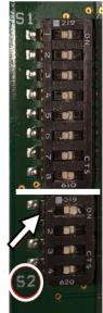
- Set dip-switch "S2" #1 to "ON". The solar option is to be used for the heat pump.
- Check Jandy documentation for any further dip switch settings.
- If additional sensors are required on the external controller, install them on the external controller now.
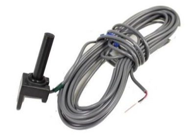
Pentair EasyTouch® and Pentair IntelliTouch® Example:
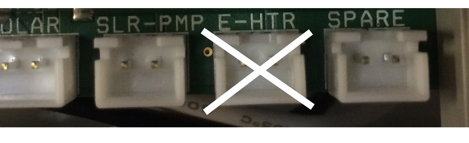
Some controllers require an additional sensor be connected to the external controller's power supply circuit board at the solar connection point. The sensor is not used, but will show an error if not connected.
- Reinstall electrical access panels on both heat pump and external controller.
- Reactivate power to heat pump and external controller.
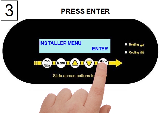
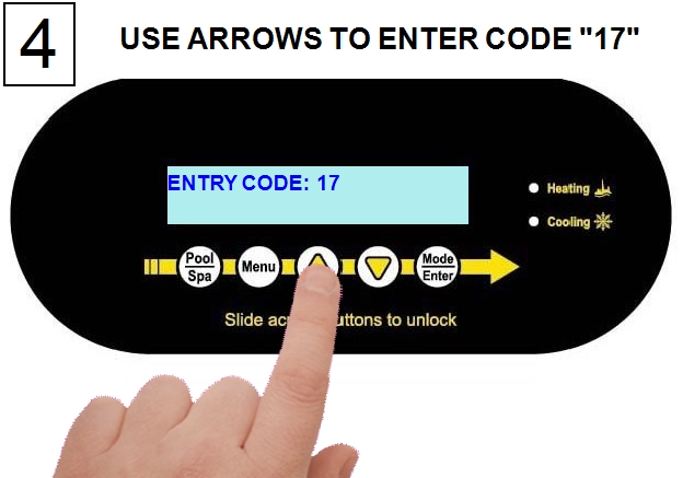
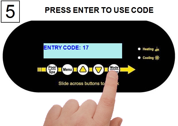
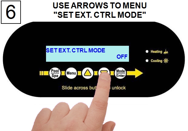
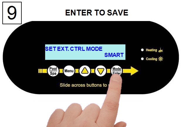
- Configure heat pump to accept external controller signal.


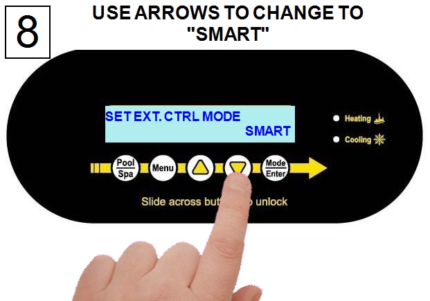
- If after 45 seconds, the heat pump displays a "SMART COMM FAULT":
- Confirm dip switches - If external controller uses dip switches, confirm switches are in the correct position. Otherwise proceed to confirm wiring.
- Deactivate power to external controller.
- Remove access panel on external controller.
- Check external controller manual for proper dip switch positioning and confirm dip switches.
- Reinstall electrical access panel.
- Reactivate power to the controller.
- If fault persists, proceed to confirming wiring.
- Confirm wiring - Confirm wires are oriented properly on the heat pump's "Port B" of the microprocessor.
- Deactivate power to heat pump and external controller.
- Remove access panel on heat pump.
- Reverse wires on "Port B".
- Reinstall electrical access panel.
- Reactivate power to the controller.
- Reactivate power to the heat pump.
- If fault continues to occur, check with manufacturer of external controller for additional advice on using a heat pump with the controller.
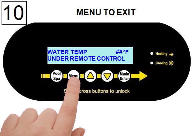
- After establishing a connection from the external controller to the heat pump, further programming will be required at the external controller.
- See external controller manuals or contact installer or manufacturer of that product.