Installation Instructions
- Turn off power to the unit at breaker panel and remove access panels. Deactivate circulation pump. Using a suitable test meter confirm that heat pump power is off.
Power Control Board Location
Confirm the new control board will fit in the electrical panel where the existing board is located.
- If the new board will not fit, an adapter plate kit is available from AquaCal (Kit #STK0274).
- For some legacy models it may be necessary to remove the metal divider between the low voltage and high voltage portions of the electrical enclosure. Do not attempt to remove the divider unless properly qualified.
Display Panel Location
If the new display does not fit, it may be necessary to alter the opening.
- If the opening is too small, it can be enlarged slightly with a file or other suitable tool.
- Remove the existing display and mount the new display. Enlarge the opening as needed. Route the display wire into the electrical panel. Secure the wire with a tie wrap so it does not shift and come in contact with the fan blade. On models with a pop out display secure the wire so it does not interfere with the operation of the mechanism.
- Photograph or label the existing control board wire connections and then remove the board.
- Photograph the wire connection locations on the new control board before installing. It can be challenging to see the labels after the new board is mounted.
- Install the new control board. Use a mounting plate if needed. For some installations it may be easier to connect the wiring before mounting the board. Reconnect the following wires as they were previously:
- HP / LP (If the unit has an LP switch, it must be wired in series with the HP switch).
- HP2 (If used. If there was no HP2 on the previous controller, leave this port empty).
- FS1
- FS2 (Typically not used)
- 24 VAC
- REV (reversing units only)
- COMP
- FAN
- FAN SPD (If there is no fan speed wire, leave this port empty)
- W" or WS1 to WS1
- WS2 or AIR to WS2
- DS1
- DS2
- If your unit is equipped with an "LP" switch, the "LP" switch and "HP" switch must now be wired in series. See Figure 3.
- Cut off one wire connector from the "HP" switch and one wire connector from the "LP" switch.
- Strip back wire on the cut LP and HP wire and connect them together in series.
- Connect the remaining wires to an (installer supplied) adapter or wire connector and attach this assembly to the "HP / LP" port on the control board.
- Discard the spade connectors that were just cut off.

Sensors
The new controller requires dual defrost and dual water temp sensors in order to operate properly. Some models may have only one water temp sensor ("WS1") and one air sensor ('AIR").
-
If the sensor connected to ("AIR") is mounted on the side of the electrical panel, it will need to be relocated to be used as a water sensor.
-
If the unit does not have two defrost sensors and two water sensors (or one AIR and one water sensor), then additional parts and instructions will need to be obtained.
- Instructions for water sensor(s) / defrost sensor(s) installation is on document LTP0209. For further assistance, please contact AquaCal.
- Water sensor which includes the hose clamp. (ECS0393).
- Defrost sensor (ECS0395)
-
DO NOT attempt to splice water temperature sensors together and not properly install water sensors. This will circumvent safety features, cause false errors, as well as void heat pump warranty.
- Inspect the water temperature sensors typically located on the water inlet piping. There should be two sensors as shown in Figure 7.
- If there is only one sensor in this location (Figure 7), and it is installed in a well as shown in Figure 4, the original sensor will need to be replaced or an OTA fault will occur. Replace the original sensor with AquaCal® part # STK0393.
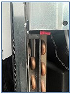
- If there is only one water temp sensor in this location, trace the wires connected to ‘AIR” on the original control board to the sensor mounting location. The AIR sensor is typically mounted on the left (out)side of the electrical compartment as shown in Figure 5.
- If your sensor is in this location, it must be relocated to the “water in” line adjacent to the primary water temp sensor (WS1). A 2 ½-3 ½ inch stainless steel hose clamp (AquaCal® part # 9158) is required. This clamp is available at most hardware stores.

-
Relocate the AIR sensor into the water line, next to the primary water temperature sensor.
- Carefully drill a 3/8” hole near the existing water temp sensor, a small step drill bit is recommended. See Figure 6.
- Be careful not to over drill and make the hole too large. Use a sharpie to mark a stopping point.
- Make sure that there is sufficient clearance to install new hose clamp.
- Make sure that the sensors are not in line with each other. They should be staggered on the PVC pipe so that incoming water flow will hit each sensor equally. See Figure 7. In other words, not have one sensor "blocking" the full water flow of the other sensor.
- Ensure that the sensor is far enough inside to put the panel back on.
- Remove any burrs from the pipe before installing a new sensor using sand paper.
- Attach sensor using a new clamp.
- Snug but do not over tighten hose clamp.
- Activate circulation pump and check for leaks.
- Carefully drill a 3/8” hole near the existing water temp sensor, a small step drill bit is recommended. See Figure 6.
- Route the new water temperature sensor wires into the electrical panel and connect them to "WS1" and "WS2'. Using the tie wraps provided secure the wires so they do not touch or chafe on any refrigerant piping or sharp edges.


- When the board is powered up the user will be prompted to enter the Model number and Serial number. Refer to the data plate on the metal electrical panel cover to enter these numbers.
- Refer to the AquaCal® installation manuals online for operation, programming and additional set up information. https://www.aquacal.com/heatpump-manuals/