Installation Instructions
- Turn off power to the unit at breaker panel and remove access panels. Deactivate circulation pump. Using a suitable test meter confirm that heat pump power is off.
Power Control Board Location
Confirm the new control board will fit in the electrical panel where the existing board is located.
- If the new board will not fit, an adapter plate kit is available from AquaCal (Kit #STK0274).
- For some legacy models it may be necessary to remove the metal divider between the low voltage and high voltage portions of the electrical enclosure. Do not attempt to remove the divider unless properly qualified.
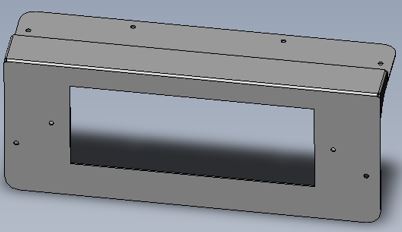
Display Panel Location
If the new display does not fit, it may be necessary to alter the opening.

- Tag and label each wire before disconnecting it from the controller board. (Masking tape and fine tip sharpie work well for this).
- Remove all wires.
- Remove the screws securing the board, remove the HP7 control board and mount the new board. It may be helpful to take several close up photos of the new control board before installing to make it easier to connect the wiring to the proper terminal.

- Using the wire adapters provided reconnect all wiring.
- "24 VAC" to "24 VAC"
- "REV" to "REV"
- "COMP" to "COMP"
- "FAN" to "FAN"
- "FS1" to "FS1"
- "FS2" to "FS2" (not typically used)
- "DS" to "DS1"
- If your unit has a jumper connected to "LP", discard the jumper. Then connect the "HP" wire to "HP / LP".
- If your unit is equipped with an "LP" switch, the "LP" switch and "HP" switch must now be wired in series. See Figure 9.
- Cut off one wire connector from the "HP" switch and one wire connector from the "LP" switch.
- Strip back wire on the cut LP and HP wire and connect them together in series.
- Connect the remaining wires to one of the adapters provided and attach this assembly to "HP / LP".
- Discard the spade connectors that were just cut off.
- For reversing models, with single speed fans, that use an additional red wire connected to the yellow 24-Volt control board connection (Figure 10)
- Remove the red wire and tape it off. This wire will no longer be used.
- Remove and discard the dual tab adapter.

- For reversing models, with 2 speed fans that have a second fan speed relay. See "Optional Two Speed Fan Configuration for Reversing Models".
Sensors
The new controller requires dual defrost and dual water temp sensors in order to operate properly.
-
Install both new water temp sensors included in the kit. Failure to replace both sensors may result in an OTA fault.
- Carefully drill a 3/8” hole near the existing water temp sensor, a small step drill bit is recommended. See Figure 11.
- Be careful not to over drill and make the hole too large. Use a sharpie to mark a stopping point.
- Make sure that there is sufficient clearance to install new hose clamp.
- Make sure that the sensors are not in line with each other. They should be staggered on the PVC pipe so that incoming water flow will hit each sensor equally. See Figure 12. In other words, not have one sensor "blocking" the full water flow of the other sensor.
- Ensure that the sensor is far enough inside to put the panel back on.
- Remove any burrs from the pipe before installing a new sensor using sand paper.
- Attach sensor using a new clamp. See Figure 12.
- Snug but do not over tighten hose clamp.
- Activate circulation pump and check for leaks.
- Carefully drill a 3/8” hole near the existing water temp sensor, a small step drill bit is recommended. See Figure 11.
- Route the new water temperature sensor wires into the electrical panel and connect them to "WS1" and "WS2'. Using the tie wraps provided secure the wires so they do not touch or chafe on any refrigerant piping or sharp edges.

- If the existing water temp sensor is mounted inside a temperature well (Figure 13) or is a different style than the sensor shown in the kit (See "ECS0394 Water Temperature Sensor".), abandon it in place and install both new water temp sensors on the 'Water In" pipe, just inside the electrical panel as shown in Figure 12.

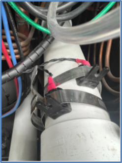
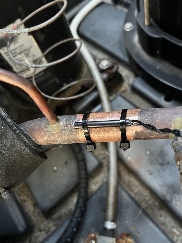
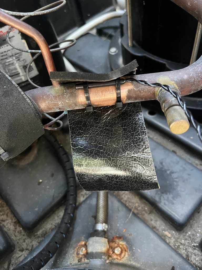
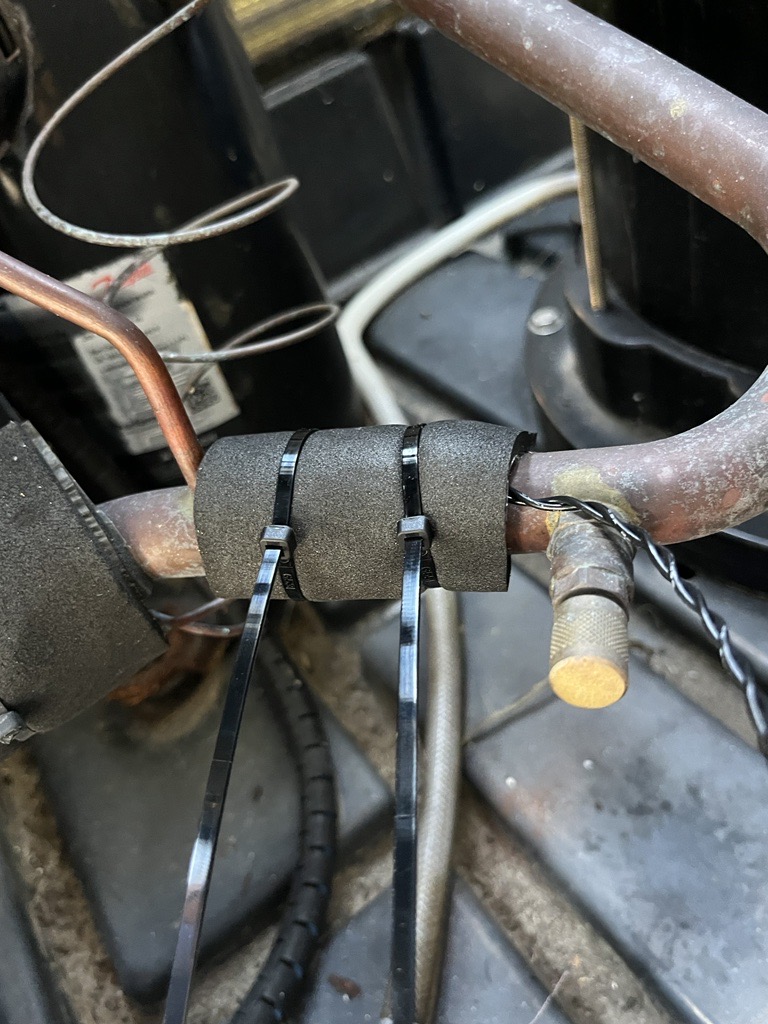
- Secure the other temp sensor (defrost), provided in the kit, to the suction line (the larger copper refrigerant line) near the compressor as shown. See Figure 14, Figure 15, and Figure 16. Using included insulation, wrap sensor and tie wrap in place.
- Route the new defrost temp sensor into the electrical panel and connect to "DS2". Using the tie wraps provided, secure the wires so they do not touch or chafe on any refrigerant piping or sharp edges.
- Remove the old display panel.
- Install the new display panel, being careful to route the cable in the same location as the original and connect to the control board's port labeled LCD DISPLAY". Secure the cable as needed to prevent chafing or the fan blade from hitting it.
- Reinstall panels, restore power, and test operation.